Thursday 25 May 2023

What is Switch Port Analyzer SPAN, RSPAN? How to configure SPAN and RSPAN?

  What are SPAN and RSPAN?

Cisco Catalyst Switches have a feature called SPAN (Switch Port Analyzer). This feature is used for directing all traffic from a source port or source VLAN to a single port. Or in other words this feature copies all traffic from a source port or source VLAN to a destination interface. sometimes SPAN is referred to as session monitoring because of the commands used to configure SPAN.  

Switch Port Analyzer is very useful for many applications and also a number of reasons:

  • SPAN is useful for data collection purposes.
  • If you want to use Wireshark to capture traffic from an interface that is connected to a workstation, server, phone, or anything else you want to sniff.
  • all traffic from VoIP VLAN can be delivered to a single switch port to so you can record the calls in a VoIP network.
  •  Another common use of this feature is to (IDS/IPS)


SPAN session source can be a port or ports and VLAN. This is why this offers us great flexibility in monitoring traffic. we can be transmitted, received, or both directions to the destination interface.

If the destination port for SPAN is on the Local switch (same switch) this we call SPAN. If the destination SPAN is on a different switch, then we call this remote SPAN or RSPAN.

In RSPAN, a specific VLAN need to be configured across the entire switching path from the source port or VLAN to the RSPAN destination port to carry the traffic that you are copying. So, the traffic can travel from the source switch to the destination switch. This requires that the RSPAN VLAN be included in any trunk in that path too.  


 Restriction of SPAN and RSPAN.

  • You can configure the source interface whatever you want switch port, routed port, access port, trunk port, EtherChannel, etc but you can’t mix interfaces and VLANs.
  • Do not overload an interface with the entire VLAN.
  • When you configure the destination interface (port). The previous configuration is overwritten. When you remove the SPAN configuration the original configuration is restored.
  • Destination port do not support any layer 2 protocol like STP, CDP, VTP, DTP, etc.
  • Destination port do not support port security.
  • Destination port do not support private VLAN.


 let's configure, the SPAN witch source VLAN. 


Topology: -


  •  configure the topology as per the diagram
  • assign the IP to their port as per the topology 
  • configure monitor session on the switch 
  • configure fa0/2 to 5 as the source port
  • test the lab

  • remove the configuration 
  • configure source VLAN
  • verify the Lab

  • assign the IP to PCs

:\>ipconfig

IP Address......................: 10.1.1.1

Subnet Mask.....................: 255.0.0.0

Default Gateway.................: 0.0.0.0


:\>ipconfig

IP Address......................: 10.1.1.2

Subnet Mask.....................: 255.0.0.0

Default Gateway.................: 0.0.0.0


:\>ipconfig

IP Address......................: 10.1.1.3

Subnet Mask.....................: 255.0.0.0

Default Gateway.................: 0.0.0.0


:\>ipconfig

IP Address......................: 10.1.1.4

Subnet Mask.....................: 255.0.0.0

Default Gateway.................: 0.0.0.0


Switch(config)#monitor session 1 source interface fastEthernet 0/2 - 5

Switch(config)#monitor session 1 source interface fastEthernet 0/2 - 5


Switch#show monitor session 1

Session 1

---------

Type : Local Session

Description : -

Source Ports :

Both : Fa0/2,Fa0/3,Fa0/4,Fa0/5

Destination Ports : Fa0/1

Encapsulation : Native

Ingress : Disabled


Switch#show monitor detail

Session 1

---------

Type : Local Session

Description : -

Source Ports :

RX Only : None

TX Only : None

Both : Fa0/2,Fa0/3,Fa0/4,Fa0/5

Source VLANs :

RX Only : None

TX Only : None

Both : None

Source RSPAN VLAN : None

Destination Ports : Fa0/1

Encapsulation : Native

Ingress : Disabled

Filter VLANs : None

Dest RSPAN VLAN : None


(Now generate some traffic using ping from PCs and then open our sniffer)


(As you can see our sniffer received a copy of the data. now we are going to monitor from VLAN)


Switch(config)#vlan 10

Switch(config-vlan)#name SPAN-TEST

Switch(config-vlan)#

Switch(config-vlan)#EXIT


Switch(config)#monitor session 2 source vlan 10 both

Switch(config)#monitor session 2 destination interface fastEthernet 0/1

Switch(config)#exit


Switch#show monitor session 2

Session 2

---------

Type : Local Session

Description : -

Source VLANs :

Both : 10

Destination Ports : Fa0/1

Encapsulation : Native

Ingress : Disabled


(Generate some traffic using ping from PCs)


Sunday 21 May 2023

What is NetFlow and Flexible NetFlow? How to configure NetFlow?

 NetFlow is a software feature set in Cisco IOS that is designed to provide network administrators information about what is happening in the network. NetFlow is a protocol that monitors and analyzes network traffic flow. NetFlow has been included in Cisco IOS for a long time and has evolved through several versions 1, 5, and 9 current version is 9. It's also called Cisco Flexible NetFlow.

 Flexible NetFlow is an extension of Traditional NetFlow. it is advanced and next-generation NetFlow technology. This flexible NetFlow provides deep packet inspection with uses NBAR for 2 to 7 layers of data can be analyzed.

We have three types of flows in flexible NetFlow

Normal cache

Permanent cache

Immediate cache


Flexible NetFlow components are: -

Records: flow are a set of predefined and user-defined key fields such as source IP address, source port destination IP address, and so on).

Flow monitors: this component is used to monitor network traffic. this is applied to an interface, flow monitor includes records, cache, and optionally a flow exporter. this component (flow monitor) collects information about flows.

Flow exporters: flow exporters export the cached flow information to a server running a NetFlow collector.

Flow samplers: this component is used to reduce the load on NetFlow-enabled devices. Sampler allows specifying the sample size of traffic.


Let’s configure NetFlow components one by one


 Topology:


Goal:

  • configure the topology as per the diagram 
  • configure IP addresses as per the topology 
  • configure routing between routers
  • configure Flow Record 
  • configure Exporter flow
  • configure Monitor flow
  • verify with show commands  


R1(config)#interface ethernet 3/0
R1(config-if)#ip address 10.1.1.1 255.0.0.0
R1(config-if)#no shutdown
R1(config-if)#exit

R1(config)#interface fastEthernet 1/1
R1(config-if)#ip address 192.168.1.1 255.255.255.0
R1(config-if)#no shutdown
R1(config-if)#exit


R1(config)#do show ip int br
Interface                  IP-Address      OK? Method Status                Protocol
FastEthernet1/1      192.168.1.1     YES manual up                    up
Ethernet3/0                10.1.1.1        YES manual up                    up


R2(config)#interface fastEthernet 1/1
R2(config-if)#ip address 192.168.1.2 255.255.255.0
R2(config-if)#no shutdown
R2(config-if)#exit

R2(config)#interface fastEthernet 0/0
R2(config-if)#ip address 20.1.1.1 255.0.0.0
R2(config-if)#no shutdown
R2(config-if)#exit


R2(config)#do show ip int br
Interface                  IP-Address      OK? Method Status                Protocol
FastEthernet0/0            20.1.1.1        YES manual up                    up
FastEthernet1/1            192.168.1.2     YES manual up                    up


(Assigning IP addresses on PCs)

PC1> show ip all

NAME   IP/MASK              GATEWAY           MAC                DNS
PC1    10.1.1.2/8           10.1.1.1          00:50:79:66:68:01

PC2> show ip all

NAME   IP/MASK              GATEWAY           MAC                DNS
PC2    10.1.1.3/8           10.1.1.1          00:50:79:66:68:00

PC3> show ip all

NAME   IP/MASK              GATEWAY           MAC                DNS
PC3    10.1.1.4/8           10.1.1.1          00:50:79:66:68:03

PC4> show ip all

NAME   IP/MASK              GATEWAY           MAC                DNS
PC4    10.1.1.5/8           10.1.1.1          00:50:79:66:68:02


PC5> show ip all

NAME   IP/MASK              GATEWAY           MAC                DNS
PC5    10.1.1.6/8           10.1.1.1          00:50:79:66:68:04

PC6> show ip all

NAME   IP/MASK              GATEWAY           MAC                DNS
PC6    10.1.1.7/8           10.1.1.1          00:50:79:66:68:05


PC7> show ip all

NAME   IP/MASK              GATEWAY           MAC                DNS
PC7    10.1.1.8/8           10.1.1.1          00:50:79:66:68:06

PC8> show ip all

NAME   IP/MASK              GATEWAY           MAC                DNS
PC8    10.1.1.9/8           10.1.1.1          00:50:79:66:68:07


PC9> show ip all

NAME   IP/MASK              GATEWAY           MAC                DNS
PC9    20.1.1.2/8           20.1.1.1          00:50:79:66:68:08


R1(config)#router eigrp 100
R1(config-router)#network 192.168.1.0
R1(config-router)#network 10.0.0.0
R1(config-router)#no auto-summary
R1(config-router)#exit

R2(config)#router eigrp 100
R2(config-router)#network 20.0.0.0
R2(config-router)#network 192.168.1.0
R2(config-router)#no auto-summary
R2(config-router)#exit

R1(config)#flow record netflow-record
R1(config-flow-record)#match ipv4 tos
R1(config-flow-record)#match ipv4 protocol
R1(config-flow-record)#match ipv4 source address
R1(config-flow-record)#match ipv4 destination address
R1(config-flow-record)#match transport source-port
R1(config-flow-record)#match transport destination-port
R1(config-flow-record)#match interface input
R1(config-flow-record)#collect interface output
R1(config-flow-record)#collect counter bytes
R1(config-flow-record)#collect counter packet
R1(config-flow-record)#exit


R1#show flow record netflow-record
flow record netflow-record:
  Description:        User defined
  No. of users:       0
  Total field space:  30 bytes
  Fields:
    match ipv4 tos
    match ipv4 protocol
    match ipv4 source address
    match ipv4 destination address
    match transport source-port
    match transport destination-port
    match interface input
    collect interface output
    collect counter bytes
    collect counter packets


R1(config)#flow exporter netflow-exporter
R1(config-flow-exporter)#destination 192.168.1.2
R1(config-flow-exporter)#export-protocol netflow-v9
R1(config-flow-exporter)#transport udp 9999
R1(config-flow-exporter)#exit
R1(config)#end

R1#show flow exporter netflow-exporter
Flow Exporter netflow-exporter:
  Description:              User defined
  Export protocol:          NetFlow Version 9
  Transport Configuration:
    Destination IP address: 192.168.1.2
    Source IP address:      192.168.1.1
    Transport Protocol:     UDP
    Destination Port:       9999
    Source Port:            62882
    DSCP:                   0x0
    TTL:                    255
    Output Features:        Not Used


(Generate traffic flow using ping from PCs)


R1#show ip cache flow
IP packet size distribution (356 total packets):
   1-32   64   96  128  160  192  224  256  288  320  352  384  416  448  480
   .050 .050 .898 .000 .000 .000 .000 .000 .000 .000 .000 .000 .000 .000 .000

    512  544  576 1024 1536 2048 2560 3072 3584 4096 4608
   .000 .000 .000 .000 .000 .000 .000 .000 .000 .000 .000

IP Flow Switching Cache, 4456704 bytes
  10 active, 65526 inactive, 85 added
  1554 ager polls, 0 flow alloc failures
  Active flows timeout in 30 minutes
  Inactive flows timeout in 15 seconds
IP Sub Flow Cache, 533256 bytes
  0 active, 16384 inactive, 0 added, 0 added to flow
  0 alloc failures, 0 force free
  1 chunk, 1 chunk added
  last clearing of statistics never
Protocol         Total    Flows   Packets Bytes  Packets Active(Sec) Idle(Sec)
--------         Flows     /Sec     /Flow  /Pkt     /Sec     /Flow     /Flow
UDP-other           18      0.0         1    28      0.0       0.0      15.5
ICMP                57      0.0         5    82      0.0       4.2      15.4
Total:              75      0.0         4    79      0.0       3.2      15.4

SrcIf         SrcIPaddress    DstIf         DstIPaddress    Pr SrcP DstP  Pkts
Fa1/1         20.1.1.2        Et3/0*        10.1.1.5        01 0000 0800     5
Et3/0         10.1.1.9        Fa1/1         20.1.1.2        01 0000 0800     5
Et3/0         10.1.1.7        Fa1/1         20.1.1.1        01 0000 0800     5
Et3/0         10.1.1.6        Fa1/1         20.1.1.2        01 0000 0800     5
Et3/0         10.1.1.8        Fa1/1         20.1.1.1        01 0000 0800     5
Et3/0         10.1.1.5        Fa1/1         20.1.1.2        01 0000 0000     5
Fa1/1         20.1.1.2        Et3/0*        10.1.1.9        01 0000 0000     5
Fa1/1         20.1.1.1        Et3/0*        10.1.1.7        01 0000 0000     5
Fa1/1         20.1.1.2        Et3/0*        10.1.1.6        01 0000 0000     5
Fa1/1         20.1.1.1        Et3/0*        10.1.1.8        01 0000 0000     5


R1(config)#flow monitor netflow-monitor
R1(config-flow-monitor)#record netflow ipv4 original-input
R1(config-flow-monitor)#cache timeout active 30
R1(config-flow-monitor)#exporter netflow-exporter
R1(config-flow-monitor)#exit
R1(config)#end

R1#show flow monitor
Flow Monitor netflow-monitor:
  Description:       User defined
  Flow Record:       netflow ipv4 original-input
  Flow Exporter:     netflow-exporter (inactive)
  Cache:
    Type:              normal
    Status:            not allocated
    Size:              4096 entries / 0 bytes
    Inactive Timeout:  15 secs
    Active Timeout:    30 secs
    Update Timeout:    1800 secs


R1(config)#interface ethernet 3/0
R1(config-if)#ip flow monitor netflow-monitor input
R1(config-if)#ip flow monitor netflow-monitor output
R1(config-if)#exit


R1#show flow monitor netflow-monitor statistics
  Cache type:                            Normal
  Cache size:                              4096
  Current entries:                            0
  High Watermark:                            18

  Flows added:                               22
  Flows aged:                                22
    - Active timeout   (    30 secs)          0
    - Inactive timeout (    15 secs)         22
    - Event aged                              0
    - Watermark aged                          0
    - Emergency aged                          0


(Generate traffic flow using ping from PCs)


R1#show flow monitor netflow-monitor cache
  Cache type:                            Normal
  Cache size:                              4096
  Current entries:                            0
  High Watermark:                            18

  Flows added:                               22
  Flows aged:                                22
    - Active timeout   (    30 secs)          0
    - Inactive timeout (    15 secs)         22
    - Event aged                              0
    - Watermark aged                          0
    - Emergency aged                          0

There are no cache entries to display.

R1#show flow monitor netflow-monitor cache
  Cache type:                            Normal
  Cache size:                              4096
  Current entries:                            4
  High Watermark:                            18

  Flows added:                               26
  Flows aged:                                22
    - Active timeout   (    30 secs)          0
    - Inactive timeout (    15 secs)         22
    - Event aged                              0
    - Watermark aged                          0
    - Emergency aged                          0

IPV4 SOURCE ADDRESS:       192.168.1.2
IPV4 DESTINATION ADDRESS:  10.1.1.4
TRNS SOURCE PORT:          49206
TRNS DESTINATION PORT:     33437
INTERFACE INPUT:           Fa1/1
FLOW SAMPLER ID:           0
IP TOS:                    0x00
IP PROTOCOL:               17
ip source as:              0
ip destination as:         0
ipv4 next hop address:     10.1.1.4
ipv4 source mask:          /24
ipv4 destination mask:     /8
tcp flags:                 0x00
interface output:          Et3/0
counter bytes:             28
counter packets:           1
timestamp first:           18:25:30.319
timestamp last:            18:25:30.319

IPV4 SOURCE ADDRESS:       10.1.1.4
IPV4 DESTINATION ADDRESS:  192.168.1.2
TRNS SOURCE PORT:          0
TRNS DESTINATION PORT:     771
INTERFACE INPUT:           Et3/0
FLOW SAMPLER ID:           0
IP TOS:                    0x00
IP PROTOCOL:               1
ip source as:              0
ip destination as:         0
ipv4 next hop address:     192.168.1.2
ipv4 source mask:          /8
ipv4 destination mask:     /24


Thank you so much for visiting. please click the YouTube channel link https://youtu.be/D0t29ZdO09I and subscribe. 

Tuesday 16 May 2023

What is IP SLA (Internet Protocol Service Level Agreement) How to configure IP SLA?

IP SLA (Internet protocol service level agreement) is a great feature of the Cisco Internetwork Operating System (Cisco IOS). It is used to measure the ongoing behavior of the network. the measurement can be simple as using ping where we check the round-trip time or something more advanced like a VoIP RTP packet where we check the delay, and jitter and calculate a MOS score that gives you an indication of what the voice quality will be. IP SLA primarily acts as a tool and gathers data about a network.


We can configure IP SLA on the router and then the router sends packets, receive a response, and gather information about whether a response was received and measurement delay, jitter, packet loss, response times, and latency. We can combine IP SLA with static routes, policy-based routing, and routing protocols like OSPF or EIGRP.

Why do we need it? how its work?


As you can see from the above topology, we have a customer router connected to two ISPs with serial interfaces, and also, we have configured default routes with different AD in order to provide backup if one ISP or link fails, we can switch to another ISP. Now our customer router can reach the server on the internet and it can.  

but it's not very much reliable. because as long as the interface is up and the next hop is reachable the default route will be in the routing table. now if ISP 1 is having an issue with connectivity and ISP 1 cannot reach that server on the internet but our router still uses them for all the traffic. We don’t want this to happen to prevent this we are going to combine IP SLA with default routes.

now our router is configured with IP SLA now we check end-to-end connectivity.  IP SLA ping to the server and get a reply from the server. if somehow the ping fails then we switch over to ISP2, this method is reliable. 

we can also use different measurements (operation) besides ping and RTP. 


  • TCP Connections
  • UDP
  • DNS
  • DHCP
  • HTTP
  • FTP

 let's see the configuration of IP SLA.


  • Configure the topology as per the diagram 
  • Assign the IP addresses as per our topology 
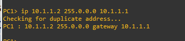
  • Assign IP on PC-1 10.1.1.2 and PC-2 40.1.1.2
  • Configure the default route between R-1 to ISP-1 Primary
  • configure default route between R-1 and ISP-2 with a backup link using AD 12
  • Configure Static route from ISPs
  • verify the backup link between R-1 and ISPs
  • configure IPSLA 
  • make sure the backup will work even ISP side link is down. 

R1(config)#interface serial 2/0
R1(config-if)#ip address 1.1.1.1 255.0.0.0
R1(config-if)#no shutdown
R1(config-if)#exit

*May 16 12:07:59.435: %LINK-3-UPDOWN: Interface Serial4/0, changed state to up
*May 16 12:08:00.435: %LINEPROTO-5-UPDOWN: Line protocol on Interface Serial4/0, changed state to up

R1(config)#interface fastEthernet 0/0
R1(config-if)#ip address 10.1.1.1 255.0.0.0
R1(config-if)#no shutdown
R1(config-if)#exit

*May 16 12:08:21.963: %LINK-3-UPDOWN: Interface FastEthernet0/0, changed state to up
*May 16 12:08:22.963: %LINEPROTO-5-UPDOWN: Line protocol on Interface FastEthernet0/0, changed state to up


R1(config)#interface serial 2/1
R1(config-if)#ip address 3.1.1.2 255.0.0.0
R1(config-if)#no shutdown
R1(config-if)#exit

*May 16 12:09:25.947: %LINEPROTO-5-UPDOWN: Line protocol on Interface Serial2/1, changed state to up
*May 16 12:11:27.531: %LINEPROTO-5-UPDOWN: Line protocol on Interface Serial2/1, changed state to up


R1#show ip interface brief
Interface                  IP-Address      OK? Method Status     Protocol
FastEthernet0/0        10.1.1.1        YES manual up                    up
Serial2/0                  1.1.1.1         YES manual up                    up
Serial2/1                  3.1.1.2         YES manual up                    up


R2(config)#interface serial 2/0

R2(config-if)#ip address 1.1.1.2 255.0.0.0

R2(config-if)#no shutdown

R2(config-if)#exit


R2(config)#interface fastEthernet 1/1

R2(config-if)#ip address 2.2.2.1 255.0.0.0

R2(config-if)#no shutdown

R2(config-if)#exit


R2#show ip interface brief

Interface                  IP-Address      OK? Method Status       Protocol

FastEthernet1/1        2.2.2.1         YES manual up                    up

Serial2/0                  1.1.1.2         YES manual up                    up


R3(config)#interface serial 2/1
R3(config-if)#ip address 3.3.3.1 255.0.0.0
R3(config-if)#no shutdown
R3(config-if)#exit

R3(config)#interface fastEthernet 1/0
R3(config-if)#ip address 4.1.1.2 255.0.0.0
R3(config-if)#no shutdown
R3(config-if)#exit


R3#show ip interface brief
Interface                  IP-Address      OK? Method Status       Protocol
FastEthernet1/0       4.1.1.2         YES manual up                    up
Serial2/1                  3.3.3.1         YES manual up                    up


R4(config)#interface fastEthernet 1/0

R4(config-if)#ip address 4.1.1.1 255.0.0.0

R4(config-if)#no shutdown

R4(config-if)#exit


R4(config)#interface fastEthernet 0/0

R4(config-if)#ip address 40.1.1.1 255.0.0.0

R4(config-if)#no shutdown

R4(config-if)#exit


R4#show ip interface brief

Interface                  IP-Address      OK? Method Status                Protocol

FastEthernet0/0            40.1.1.1        YES manual up                    up

FastEthernet1/0            4.1.1.1         YES manual up                    up

FastEthernet1/1            2.2.2.2         YES manual up                    up


PC-1


PC-2


R1(config)#ip route 0.0.0.0 0.0.0.0 1.1.1.2
R1(config)#ip route 0.0.0.0 0.0.0.0 3.1.1.1 12

R2(config)#ip route 10.0.0.0 255.0.0.0 1.1.1.1
R2(config)#ip route 40.0.0.0 255.0.0.0 2.2.2.2


R3(config)#ip route 10.0.0.0 255.0.0.0 3.1.1.2
R3(config)#ip route 40.0.0.0 255.0.0.0 4.1.1.1


R4(config)#ip route 10.0.0.0 255.0.0.0 2.2.2.1
R4(config)#ip route 10.0.0.0 255.0.0.0 4.1.1.2
R4(config)#ip route 1.0.0.0 255.0.0.0 2.2.2.1
R4(config)#ip route 3.0.0.0 255.0.0.0 4.1.1.2


\
{now ping 40.1.1.2 from PC-1}


PC1> ping 40.1.1.2 -1
84 bytes from 40.1.1.2 icmp_seq=1 ttl=61 time=90.686 ms
84 bytes from 40.1.1.2 icmp_seq=2 ttl=61 time=91.024 ms
84 bytes from 40.1.1.2 icmp_seq=3 ttl=61 time=91.986 ms
84 bytes from 40.1.1.2 icmp_seq=4 ttl=61 time=91.668 ms
84 bytes from 40.1.1.2 icmp_seq=5 ttl=61 time=91.013 ms

PC1> ping 40.1.1.2 -3
Connect   7@40.1.1.2 seq=1 ttl=61 time=105.601 ms
SendData  7@40.1.1.2 seq=1 ttl=61 time=106.607 ms
Close     7@40.1.1.2 seq=1 ttl=61 time=121.265 ms
Connect   7@40.1.1.2 seq=2 ttl=61 time=92.187 ms
SendData  7@40.1.1.2 seq=2 ttl=61 time=90.703 ms
Close     7@40.1.1.2 seq=2 ttl=61 time=106.370 ms
Connect   7@40.1.1.2 seq=3 ttl=61 time=90.521 ms
SendData  7@40.1.1.2 seq=3 ttl=61 time=107.727 ms
Close     7@40.1.1.2 seq=3 ttl=61 time=120.897 ms
Connect   7@40.1.1.2 seq=4 ttl=61 time=75.339 ms
SendData  7@40.1.1.2 seq=4 ttl=61 time=106.885 ms
Close     7@40.1.1.2 seq=4 ttl=61 time=121.503 ms
Connect   7@40.1.1.2 seq=5 ttl=61 time=106.025 ms
SendData  7@40.1.1.2 seq=5 ttl=61 time=105.729 ms
Close     7@40.1.1.2 seq=5 ttl=61 time=122.395 ms


{from the above output our PC-1 can ping 40.1.1.2 somewhere on the internet. now trace the 40.1.1.2 from router 1}


R1#traceroute 40.1.1.2

Type escape sequence to abort.
Tracing the route to 40.1.1.2

  1 1.1.1.2 16 msec 28 msec 32 msec
  2 2.2.2.2 60 msec 68 msec 52 msec
  3 40.1.1.2 76 msec 76 msec 84 msec


{as you can see router 1 is using our primary interface serial 2/0 because we made this interface primary}

{now shutdown the ISP - 1 interface serial 2/0 to ensure the backup link is working or not}


 R2(config)#interface serial 2/0
R2(config-if)#shutdown
R2(config-if)#exit

*May 16 13:25:24.551: %LINK-5-CHANGED: Interface Serial2/0, changed state to administratively down
*May 16 13:25:25.551: %LINEPROTO-5-UPDOWN: Line protocol on Interface Serial2/0, changed state to down


{now trace 40.1.1.2 from router 1 and make sure router 1 uses a backup link serial 2/1 in order to reach 40.1.1.2.}

R1#traceroute 40.1.1.2

Type escape sequence to abort.
Tracing the route to 40.1.1.2

  1 3.3.3.1 32 msec 28 msec 32 msec
  2 4.1.1.1 44 msec 60 msec 72 msec
  3 40.1.1.2 64 msec 76 msec 84 msec


{as you can see the above output router 1 is using a backup link which is serial 2/1 in the failover primary link.}


{what will happen if the interface between ISP-1 and router-4 goes down. router 1 will use a backup link or not. let's verify it, first, bring the interface UP which we shut down.} 


R2(config)#interface serial 2/0
R2(config-if)#no shutdown
R2(config-if)#exit

*May 16 13:33:07.427: %LINK-3-UPDOWN: Interface Serial2/0, changed state to up
*May 16 13:33:08.431: %LINEPROTO-5-UPDOWN: Line protocol on Interface Serial2/0, changed state to up

R2(config)#interface fastEthernet 1/1
R2(config-if)#shutdown
R2(config-if)#exit

*May 16 14:04:05.183: %LINK-5-CHANGED: Interface FastEthernet1/1, changed state to administratively down
*May 16 14:04:06.183: %LINEPROTO-5-UPDOWN: Line protocol on Interface FastEthernet1/1, changed state to down


R1#traceroute 40.1.1.1
Type escape sequence to abort.
Tracing the route to 40.1.1.1

  1 1.1.1.2 20 msec 24 msec 36 msec
  2 1.1.1.2 !H  !H  !H

R1#ping 40.1.1.1

Type escape sequence to abort.
Sending 5, 100-byte ICMP Echos to 40.1.1.1, timeout is 2 seconds:
UUUUU
Success rate is 0 percent (0/5)


R1#show run | include ip route
ip route 0.0.0.0 0.0.0.0 1.1.1.2
ip route 0.0.0.0 0.0.0.0 3.3.3.1 12

{as you can see router 1 is not using a backup link because the default route is still in the routing table and it's working but the link is down from the ISP side. now we need IP SLA to track end-to-end reachability}

(First, bring the link UP)

R2(config)#interface fastEthernet 1/1
R2(config-if)#no shutdown
R2(config-if)#exit

*May 16 14:07:36.903: %LINK-3-UPDOWN: Interface FastEthernet1/1, changed state to up
*May 16 14:07:37.903: %LINEPROTO-5-UPDOWN: Line protocol on Interface FastEthernet1/1, changed state to up


R1(config)#ip sla 1
R1(config-ip-sla)#icmp-echo 40.1.1.1 source-ip 10.1.1.1
R1(config-ip-sla-echo)#frequency 5
R1(config-ip-sla-echo)#threshold 100
R1(config-ip-sla-echo)#exit

R1(config)#ip sla schedule 1 life forever start-time now

R1(config)#track 1 ip sla 1
R1(config-track)#delay down 10 up 10

R1(config-track)#no ip route 0.0.0.0 0.0.0.0 1.1.1.2
R1(config)# ip route 0.0.0.0 0.0.0.0 1.1.1.2 track 1

R1(config)#do show track
Track 1
  IP SLA 1 state
  State is Up
    5 changes, last change 00:00:59
  Delay up 10 secs, down 10 secs
  Latest operation return code: OK
  Latest RTT (millisecs) 52
  Tracked by:
    STATIC-IP-ROUTING 0


{Now again shutdown the ISP-1 interface f1/0}

R2(config)#interface fastEthernet 1/1
R2(config-if)#shutdown
R2(config-if)#exit

*May 16 14:15:07.067: %LINK-5-CHANGED: Interface FastEthernet1/1, changed state to administratively down
*May 16 14:15:08.067: %LINEPROTO-5-UPDOWN: Line protocol on Interface FastEthernet1/1, changed state to down


R1#
R1#
*May 16 15:13:26.799: %TRACKING-5-STATE: 1 ip sla 1 state Up->Down
R1#
R1#


{above you see the message on router-1 the link is down. IP SLA track end to end now let's see router 1 switches to backup link dynamically or not}


R1#ping 40.1.1.1

Type escape sequence to abort.
Sending 5, 100-byte ICMP Echos to 40.1.1.1, timeout is 2 seconds:
!!!!!
Success rate is 100 percent (5/5), round-trip min/avg/max = 48/56/60 ms


R1#traceroute 40.1.1.1

Type escape sequence to abort.
Tracing the route to 40.1.1.1

  1 3.3.3.1 16 msec 32 msec 36 msec
  2 4.1.1.1 56 msec 60 msec 60 msec


{router-1 switch to backup link even if the ISP side link is down}

R1#show ip sla statistics
IPSLAs Latest Operation Statistics

IPSLA operation id: 1
Type of operation: icmp-echo
        Latest RTT: NoConnection/Busy/Timeout
Latest operation start time: *15:25:08.511 UTC Tue May 16 2023
Latest operation return code: Timeout
Number of successes: 42
Number of failures: 74
Operation time to live: Forever


thank you so much 


What is Virtual Router Redundancy Protocol (VRRP)? How to configure Virtual Router Redundancy Protocol (VRRP)?

 Virtual Router Redundancy Protocol (VRRP) is a gateway redundancy networking protocol used to create a virtual gateway similar to HSRP . VR...