Internetworks offers a comprehensive collection of articles and tutorials on computer networks, covering basic to advanced concepts such as data link layer, network layer, network security, and more. It’s a great starting point for beginners and a useful reference for advanced learners. A+ N+ CCNA CCNP CCIE
by Edgar C Francis
As we already know switches are very important network devices and with the help of switches we connect and maintain communication channels between various devices. we also know ethernet ports are present on our switches and with these ports, we connect our devices like routers computers, and other devices. switches identify the devices by their MAC addresses and provide the services. the important thing is we need to secure these ethernet ports so that authorized users are able to connect network securely.
here we can use the security feature of Cisco IOS Port-security to block the ethernet, fast ethernet, or Gig ports when the MAC address is different from the specified MAC on the port. we can use port security to filter traffic that is destined to or received from a specific host that is based on the host MAC address. These security features only be configured on access ports and by default this feature is disabled.
before we start our lab and come to the direct point, what I always do but before we need to understand these points.
Aging
mac-address
maximum
violation
Aging is when we configure the maximum number of MAC addresses on the particular port, we can also configure aging with the help of aging we specify how long the address on the port is secure,
once the time is expired, the MAC address on that port will be insecure, by default all addresses on a port are secured permanently. <1-1440> Aging time in minutes. Enter a value between 1 and 1440.
MAC address_ when we configure the specific MAC address in the port security command, only that device will be authorized by the switch to connect through the available port. this is also called a static mac address.
from the above output, we can see after the? mark. now have (H.H.H means configure static MAC address) and the second mode is (sticky) let's take a look at sticky.
Sticky before we understand what is sticky mode first, we must know, we have two configuration options for example
whenever we enable sticky learning on an interface, the interface converts all the dynamic secure MAC addresses, and also those that were dynamically learned before sticky learning was enabled, to sticky secure MAC addresses and adds all sticky secure MAC addresses to the running configuration. all newly on-boarded clients are considered sticky MACs.
now we know that the switch can learn MAC addresses on a secure port in one of three ways.
1. Manually the admin can manually configure a static MAC address. using the command
2. Dynamically when we configure the command switchport port-security, whatever the current source MAC address on that port device will be secured but not added in running-config. if we reboot the switch the port has to re-learn the MAC address.
switchport port-security
3. Dynamically-Sticky the admin can enable the switch to learn MAC address dynamically and stick them in running-config.
switchport port-security mac-address sticky
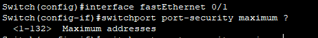
Maximum as per our requirements we can increase the limit of the number of hosts which is associated with the interface. by default, only 1 MAC address is allowed by the cisco switch on a single port. if other devices try to connect using this port our switch shutdown the port automatically. we can set this limit from 1 to 132. the maximum number is 132.
Now we have the last modeviolation
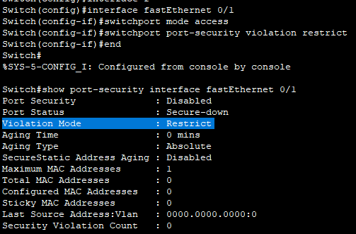
Violation_ when the MAC address of a connected device to a port is different from the list of secure addresses we are given on the interface, then a port violation occurs and the port enters the error-disable state. In violation, we have three modes. as you can see in the picture below.
Protect_ under the Protect mode the data packets from the configured MAC addresses are only transferred within the network. this mode is the least secure of the security violation mode. the port dropped the packets with unknown MAC addresses until you remove a sufficient number of MAC addresses. no syslog message is sent.
Restrict_ under the restrict mode if the security violation occurs, all the data transfer is blocked and packets are dropped. also, Syslog messages are generated simultaneously,
Shutdown_ under the shutdown mode if the violation occurs on port security enable the port. the port changed to an error-disable state. this mode is enabled by default.
{if you like this post, please take a look at our YouTube program}
Per VLAN Spanning tree (PVST) is cisco's proprietary version of STP which delivers more flexibility than the common spanning tree version. PVST works on a separate instance of STP for each VLAN. In normal
STP, CST (Common Spanning Tree), only one instance can be used for the network. There are no specific instances per VLAN. This allows the STP on each VLAN to be configured independently and offers better load balancing and tuning according to the conditions.
but as we know PVST is a cisco proprietary and because of its proprietary nature, Per VLAN Spanning tree (PVST) requires the use of a cisco inter-switch link (ISL) trunk but in coexist network where CST is working, and we configure PVST there will be problem occurs both require different trunking methods and the problem remains BPDUs are never exchanged between these types of STP.
the solution is Per-VLAN spanning tree plus (PVST+) it's also the cisco proprietary version of STP and allows the device to interoperate with both PVST and CST. PVST+ act as a translator between a group of CST switches and groups of PVST
switches. PVST+ creates an instance for each VLAN and in each instance, a different STP process occurs, a different Root bridge is selected, different port roles are used, etc.
Rapid Per VLAN Spanning Tree Plus (RPVST+) it's a Cisco proprietary STP version. Again, it has an instance for each VLAN and each VLAN has a separate STP process just like PVST but RPVST+ has a faster convergence advantage if we compare it with PVST+.
Let's see the configuration for a better understanding:
Topology:
Goal:
configure the topology as per the diagram.
configure VLANs 10,20,30 and 40 on all the switches.
configure TRUNK between switches
Allowed all VLANs on all the switches
configure PVST on all switches
configure Root bridge on switch 1 for VLAN 10
configure Root bridge on switch 2 for VLAN 20
configure Root bridge on switch 3 for VLAN 30
configure Root bridge on switch 4 for VLAN 40
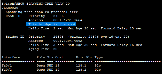
verify the configuration
SWITCH-1(config-vlan)#VLAN 10
SWITCH-1(config-vlan)#VLAN 20
SWITCH-1(config-vlan)#VLAN 30
SWITCH-1(config-vlan)#VLAN 40
SWITCH-2(config)#VLAN 10
SWITCH-2(config-vlan)#VLAN 20
SWITCH-2(config-vlan)#VLAN 30
SWITCH-2(config-vlan)#VLAN 40
SWITCH-3(config)#VLAN 10
SWITCH-3(config-vlan)#VLAN 20
SWITCH-3(config-vlan)#VLAN 30
SWITCH-3(config-vlan)#VLAN 40
SWITCH-4(config)#VLAN 10
SWITCH-4(config-vlan)#VLAN 20
SWITCH-4(config-vlan)#VLAN 30
SWITCH-4(config-vlan)#VLAN 40
SWITCH-1(config)#interface range fastEthernet 0/1-2
SWITCH-1(config-if-range)#switchport mode trunk
SWITCH-1(config-if-range)#exit
%LINEPROTO-5-UPDOWN: Line protocol on Interface FastEthernet0/1, changed state to down
%LINEPROTO-5-UPDOWN: Line protocol on Interface FastEthernet0/1, changed state to up
SWITCH-2(config)#interface range fastEthernet 0/1-2
SWITCH-2(config-if-range)#switchport mode trunk
%LINEPROTO-5-UPDOWN: Line protocol on Interface FastEthernet0/2, changed state to down
%LINEPROTO-5-UPDOWN: Line protocol on Interface FastEthernet0/2, changed state to up
SWITCH-3(config)#interface range fastEthernet 0/1-2
SWITCH-3(config-if-range)#switchport mode trunk
%LINEPROTO-5-UPDOWN: Line protocol on Interface FastEthernet0/1, changed state to down
%LINEPROTO-5-UPDOWN: Line protocol on Interface FastEthernet0/1, changed state to up
SWITCH-4(config)#interface range fastEthernet 0/1-2
SWITCH-4(config-if-range)#switchport mode trunk
%LINEPROTO-5-UPDOWN: Line protocol on Interface FastEthernet0/1, changed state to down
%LINEPROTO-5-UPDOWN: Line protocol on Interface FastEthernet0/1, changed state to up
SWITCH-1(config)#interface range fastEthernet 0/1-2
By default, our
switch dynamically learns the MAC address and stores it in the CAM table. by just looking at the source MAC address of the incoming frame.
This dynamically
learning the MAC addresses and filling in the CAM table the process is vulnerable
to layer 2 MAC address spoofing attacks. The attacker easily spoofs a few MAC
addresses to change entries in the MAC address table. We can deal with this problem by
manually configuring entries in the MAC address table. A statically configured MAC
address will always overrule dynamic entry.
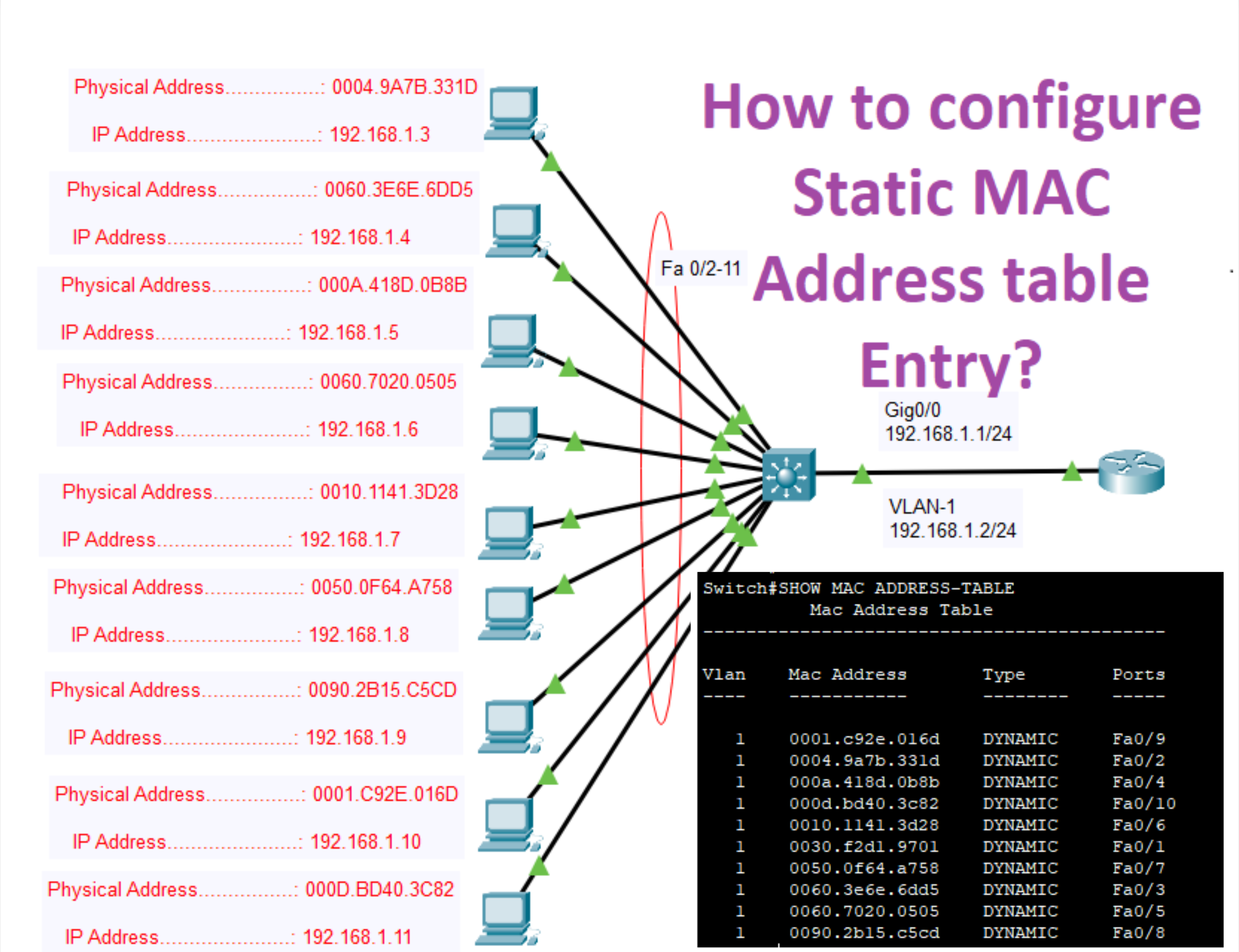
Let's configure the Static MAC Address table Entries: -
Topology:
Goal: -
configure the topology as per the diagram.
configure the IP addresses as per the topology
configure IP addresses on the PC as per the topology
Switching uses the hardware address of devices on a LAN to segment the network. Switching breaks up large collision domains into smaller domains and a collision domain is a network segment with two or more devices sharing the same bandwidth. each port on a switch is its collision domain. Layer 2 switching increases the bandwidth because each port of the switch is its self-collision domain.
Switch services bridges use software to create and manage a Content Addressable Memory (CAM) table. new switches use Application-Specific Integrated Circuits (ASICs) to build and maintain their MAC filter table.
Advantages of using Layer 2 switchings:
Hardware-based bridging
Wire-speed
Low latency
Low cost
Layer 2 switching increases the bandwidth because each switch port is its own self-collision domain.
Layer 2 Switch Functions:
Address learning layer 2 switches remember the source hardware address of each frame received on an on-interface and enter this information into a MAC database called a forward/filter table.
Forward/filter decisions when a frame is received on an interface, the switch looks at the destination hardware address, and then chooses the appropriate exit interface for it in the MAC database. This way, the frame is only forwarded out of the correct destination port.
Loop avoidance if multiple connections between switches are created for redundancy purposes, network loops can occur, and spanning tree protocol (STP) is used to prevent network.


.png)


